User login
Linea Aspera as Rotational Landmark for Tumor Endoprostheses: A Computed Tomography Study
The distal or proximal femur with tumor endoprosthesis is commonly replaced after segmental resections for bone tumors, complex trauma, or revision arthroplasty. In conventional joint replacements, correct rotational alignment of the component is referenced off anatomical landmarks in the proximal or distal femur. After tumor resection, however, these landmarks are often not available for rotational orientation. There are no reports of studies validating a particular method of establishing rotation in these cases.
To establish a guide for rotational alignment of tumor endoprostheses, we set out to define the natural location of the linea aspera (LA) based on axial computed tomography (CT) scans. The LA is often the most outstanding visible bony landmark on a cross-section of the femur during surgery, and it would be helpful to know its normal orientation in relation to the true anteroposterior (AP) axis of the femur and to the femoral version. We wanted to answer these 5 questions:
1. Is the prominence of the LA easily identifiable on cross-section at different levels of the femoral shaft?
2. Does an axis passing through the LA correspond to the AP axis of the femur?
3. If not, is this axis offset internally or externally and by how much?
4. Is this offset constant at all levels of the femoral shaft?
5. How does the LA axis relate to the femoral neck axis at these levels?
The answers determine if the LA can be reliably used for rotational alignment of tumor endoprostheses.
Materials and Methods
After this study received Institutional Review Board approval, we retrospectively reviewed whole-body fluorine-18-deoxyglucose (FDG) positron emission tomography–computed tomography (PET-CT) studies performed in our hospital between 2003 and 2006 to identify those with full-length bilateral femur CT scans. These scans were available on the hospital’s computerized picture archiving system (General Electric). Patients could be included in the study as long as they were at least 18 years old at time of scan and did not have any pathology that deformed the femur, broke a cortex, or otherwise caused any gross asymmetry of the femur. Of the 72 patients with full-length femur CT scans, 3 were excluded: 1 with a congenital hip dysplasia, 1 with an old, malunited femoral fracture, and 1 who was 15 years old at time of scan.
Axial Slice Selection
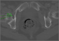
For each patient, scout AP films were used to measure femoral shaft length from the top of the greater trochanter to the end of the lateral femoral condyle. The levels of the proximal third, midshaft, and distal third were then calculated based on this length. The LA was studied on the axial slices nearest these levels. Next, we scrolled through the scans to identify an axial slice that best showed the femoral neck axis. The literature on CT measurement of femoral anteversion is varied. Some articles describe a technique that uses 2 superimposed axial slices, and others describe a single axial slice.1-3 We used 1 axial slice to draw the femoral neck axis because our computer software could not superimpose 2 images on 1 screen and because the CT scans were not made under specific protocols to measure anteversion but rather were part of a cancer staging work-up. Axial cuts were made at 5-mm intervals, and not all scans included a single slice capturing the head, neck, and greater trochanter. Therefore, we used a (previously described) method in which the femoral neck axis is drawn on a slice that most captured the femoral neck, usually toward its base.4 Last, in order to draw the posterior condyle (PC) axis, we selected an axial slice that showed the posterior-most aspects of the femoral condyles at the intercondylar notch.
Determining Anteroposterior and Posterior Condyle Axes of Femur
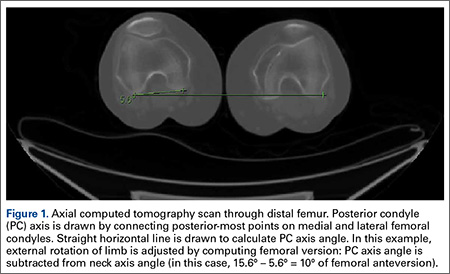
As we made all measurements for each femur off a single CT scan, we were able to use a straight horizontal line—drawn on-screen with a software tool—as a reference for measuring rotation. On a distal femur cut, the PC axis is drawn by connecting the posterior-most points of both condyles. The software calculates the angle formed—the PC angle (Figure 1). This angle, the degree to which the PC axis deviates from a straight horizontal line on-screen, can be used to account for gross rotation of the limb on comparison of images. The AP axis of the femur is the axis perpendicular to the PC axis. As such, the PC angle can also be used to determine degree of deviation of the AP axis from a straight vertical line on-screen. The AP axis was used when calculating the LA axis at the various levels of the femur (Figure 2).
Femoral Version
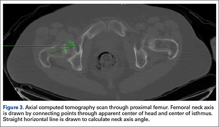
We used the software tool to draw the femoral neck axis. From the end of this line, a straight horizontal line is drawn on-screen (Figure 3). The software calculates the angle formed—the femoral neck axis angle. We assigned a positive value for a femoral head that pointed anteriorly on the image and a negative value for a head that pointed posteriorly. Adjusting for external rotation of the limb involved calculating the femoral version by subtracting the PC angle from the neck axis angle; adjusting for internal rotation involved adding these 2 angles.
Linea Aspera Morphology
After viewing the first 20 CT scans, we identified 3 types of LA morphology. Type I presents as a thickening on the posterior cortex with a sharp apex; type II presents as a flat-faced but distinct ridge of bone between the medial and lateral lips; and in type III there is no distinct cortical thickening with blunted medial and lateral lips; the latter is always more prominent.
Linea Aspera Axis Offset
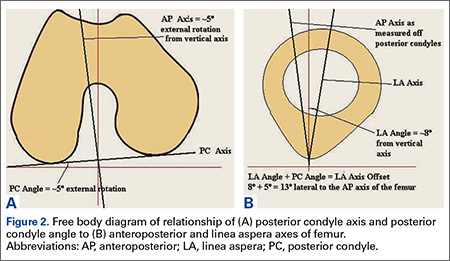
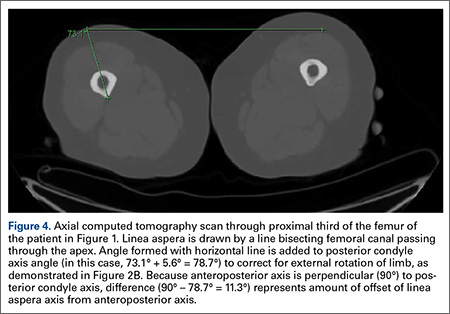
From the most posterior point of the LA, a line drawn forward bisecting the femoral canal defined the LA axis. In type I morphology, the posterior-most point was the apex; in type II, the middle of flat posterior surface was used as the starting point; in type III, the lateral lip was used, as it was sharper than the medial lip. This line is again referenced with a straight horizontal line across the image. The PC angle is then added to account for limb rotation, and the result is the LA angle. As the AP axis is perpendicular to the PC axis, the LA angle is subtracted from 90°; the difference represents the amount of offset of the LA axis from the AP axis. By convention, we assigned this a positive value for an LA lateral to the midpoint of the femur and a negative value for an LA medial to the midpoint (Figure 4).
Linea Aspera Axis and Femoral Neck Axis
The angle between the LA axis and the PC axis was measured. The femoral version angle was subtracted from that angle to obtain the arc between the LA axis and the femoral neck axis.
Statistical Analyses
All analyses were performed with SAS 9.1 (SAS Institute). All tests were 2-sided and conducted at the .05 significance level. No adjustments were made for multiple testing. Statistical analysis was performed with nonparametric tests and without making assumptions about the distribution of the study population. Univariate analyses were performed to test for significant side-to-side differences in femoral length, femoral version angle, and LA torsion angles at each level. A multivariate analysis was performed to test for interactions between sex, side, and level. In all analyses, P < .05 was used as the cutoff value for statistical significance.
Results
Femoral lengths varied by side and sex. The left side was longer than the right by a mean of 1.3 mm (P = .008). With multivariate analysis taking into account sex and age (cumulated per decade), there was still a significant effect of side on femoral length. Sex also had a significant effect on femoral length, with females’ femurs shorter by 21.7 mm (standard error, 5.0 mm). Mean (SD) anteversion of the femoral neck was 7.9° (12.7°) on the left and 13.3° (13.0°) on the right; the difference between sides was significant (P < .001). In a multivariate analysis performed to identify potential predictors of femoral version, side still had a significant (P < .001) independent effect; sex and age did not have an effect.
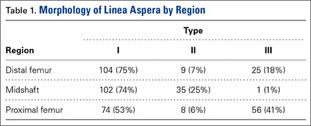
LA morphology varied according to femoral shaft level (Table 1). The morphology was type I in 75% of patients at the distal femur and 74% of patients at the midshaft femur, while only 53% of patients had a type I morphology at the proximal femur. The proportion of type III morphology was larger in the proximal femur (41%) than in the other locations.
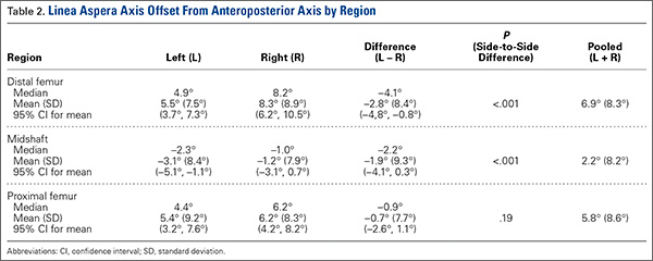
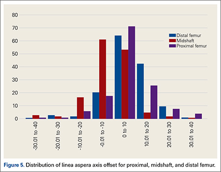
The LA axis of the femur did not correspond exactly to the AP axis at all femoral levels. At the distal femur, mean (SD) lateral offset of the LA axis was 5.5° (7.5°) on the left and 8.3° (8.9°) on the right. At the midshaft, mean (SD) medial offset of the LA axis was 3.1° (8.4°) on the left and 1.2° (7.9°) on the right. At the proximal femur, mean (SD) lateral offset of the LA axis was 5.4° (9.2°) on the left and 6.2° (8.3°) on the right. The side-to-side differences were statistically significant for the distal femur and midshaft but not the proximal femur. Table 2 lists the 95% confidence intervals for the mean values. As the range of differences was small (0.7°-2.8°), and the differences may not be clinically detected on gross inspection during surgery, we pooled both sides’ values to arrive at a single mean for each level. The LA axis was offset a mean (SD) of 6.9° (8.3°) laterally at the distal femur, 2.2° (8.2°) medially at the midshaft, and 5.8° (8.6°) laterally at the proximal femur. Figure 5 shows the frequency of distribution of LA axis offset.Offset of the LA axis from the AP axis of the femur was significantly (P < .001) different for each femoral level, even when a multivariate analysis was performed to determine the effect of sex, age, or side. Age and sex had no significant effect on mean offset of LA axis from AP axis.
We compared the mean arc between femoral neck axis and LA axis after referencing both off the PC axis. At the distal femur, mean (SD) arc between these 2 axes was 76.6° (13.1°) on the left and 68.3° (13.6°) on the right (mean difference, 8.3°); at the midshaft, mean (SD) arc was 85.2° (13.5°) on the left and 77.9° (13.1°) on the right (mean difference, 7.4°); at the proximal femur, mean (SD) arc was 76.7° (11.9°) on the left and 70.5° (12.8°) on the right (mean difference, 6.2°). The side-to-side differences were statistically significant (P < .001) for all locations.
In multivariate analysis, sex and age did not have an effect on mean arc between the 2 axes. Side and femoral level, however, had a significant effect (P < .001).
Discussion
In total hip arthroplasty, the goal is to restore femoral anteversion, usually referenced to the remaining femoral neck segment.3 In total knee arthroplasty (TKA), proper rotation preserves normal patellofemoral tracking.5 Various landmarks are used, such as the PCs or the epicondyles. After tumor resections, these landmarks are often lost.6 However, there are no reports of studies validating a particular method of achieving proper rotational orientation of tumor endoprostheses, though several methods are being used. One method involves inserting 2 drill bits before osteotomy—one proximal to the intended level of resection on the anterior femur, and the other on the anterior tibial shaft. The straight line formed can establish a plane of rotation (and length), which the surgeon must aim to restore when the components are placed. This method is useful for distal femur resections but not proximal femur resections. Another method, based on the LA’s anatomical position on the posterior aspect of the femur,4 uses the prominence of the LA to align the prosthesis. With this method, the LA is assumed to be directly posterior (6 o’clock) on the femur. However, this assumption has not been confirmed by any study. A third method, described by Heck and Carnesale,5 involves marking the anterior aspect of the femur after resection and aligning the components to it. The authors cautioned against using the LA as a landmark, saying that its course is highly variable.
The LA is a narrow, elevated length of bone, with medial and lateral lips, that serves as an attachment site for muscles in the posterior thigh. Proximally, the LA presents with lateral, medial, and intermediate lips. In the midshaft, it is often elevated by an underlying bony ridge or pilaster complex. Distally, it diverges into 2 ridges that form the triangular popliteal surface.1,7 For the LA to be a reliable landmark, first it must be clearly identifiable on viewing a femoral cross-section. The LA that presents with type I or II morphology is distinctly identifiable, and an axis from its apex and bisecting the canal can easily be constructed. In our study, the LA presented with type I or II morphology in 82% of distal femoral sections and 99% of midshaft femoral sections. Therefore, the LA is a conspicuous landmark at these levels. In the proximal femur, 59% had type I or II morphology. Type III morphology could be identified on cross-sections by the persisting prominence of the lateral lip. However, it may be difficult to appreciate the LA with this morphology at surgery.
Once the LA is identified, its normal cross-sectional position must be defined. One way to do this is to establish the relationship of its axis (LA axis) to the true AP axis. Based on mean values, the LA axis is laterally offset 7º at the distal third of the femur, medially offset 2º at the midshaft, and laterally offset 6º at the proximal third. Therefore, for ideal placement with the LA used for orientation, the component must be internally rotated 7º relative to the LA for femoral resection at the distal third, externally rotated 2º for resection at the midshaft, and internally rotated 6º for resection at the proximal third. Studies have demonstrated that joint contact forces and mechanical alignment of the lower limb can be altered with as little as 5º of femoral malrotation.8,9 Although such a small degree of malrotation is often asymptomatic, it can have long-term effects on soft-tissue tension and patellar tracking.10,11 Rotating-platform mobile-bearing TKA designs can compensate for femoral malrotation, but they may have little to no effect on patellar tracking.12 Therefore, we think aligning the components as near as possible to their natural orientation can prove beneficial in long-term patient management.
Another way of defining the normal cross-sectional position of the LA is to relate it to the femoral neck axis. We measured the difference between these 2 axes. Mean differences were 72º (distal femur), 81.5º (midshaft), and 73.5º (proximal third). Mean arc differences at all levels were larger on the left side—a reflection of the femoral neck being less anteverted on that side in our measurements. Standard deviations were smaller for measurements of LA axis offset from AP axis (range, 7.5°-9.2°) than for measurements of arc between LA axis and femoral neck axis (range, 11.9°-13.6°). This finding indicates there is less variation in the former method, making it preferable for defining the cross-sectional position of the LA.
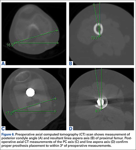
It has been said that the course of the LA is variable, and our data provide confirmation. The LA does not lie directly posterior (6 o’clock), and it does not trace a straight longitudinal course along the posterior femur, as demonstrated by the different LA axis offsets at 3 levels. However, we may still use it as a landmark if we remain aware how much the LA is offset from the AP axis at each femoral level. Figures 6A-6D, which show CT scans of a patient who underwent distal femoral resection and replacement with an endoprosthesis, illustrate how the LA axis was measured before surgery and how proper prosthesis placement was confirmed after surgery.
In hip arthroplasty, restoration of normal femoral version is the reference for endoprosthetic placement. The literature on “normal” femoral anteversion varies with the method used. In a review of studies on CT-measured adult femoral version, reported values ranged from 6.3° to 40°.2 Mean femoral version in our study ranged from 8° to 13°. Orthopedics textbooks generally put the value at 10° to 15º, and this seems to be the range that surgeons target.6 However, we found a statistically significant mean side-to-side difference of 5.4°. This finding is possibly explained by our large sample—it was larger than the samples used in other studies of CT-measured femoral version. Other studies have found mean side-to-side differences of up to 4.0º.5 Another explanation for our finding is that the studies may differ methodologically. The studies that established values for femoral anteversion were based on CT protocols—thinner slices (1-5 mm), use of foot holders to standardize limb rotation, use of 2 axial cuts in proximal femur to establish femoral neck axis2,13—designed specifically for this measurement. As the CT scans reviewed in our study are not designed for this purpose, errors in femoral version measurement may have been introduced, which may also explain why there is larger variation in measurements of the arc between the LA axis and the femoral neck axis.
Conclusion
The LA does not lie directly on the posterior surface of the femur. It deviates 6.9° laterally at the distal femur, 2.2° medially at the midshaft, and 6.9° laterally at the proximal third. As the LA is an easily identifiable structure on cross-sections of the femoral shaft at the midshaft and distal third of the femur, it may be useful as a rotational landmark for resections at these levels if these deviations are considered during tumor endoprosthetic replacements.
1. Desai SC, Willson S. Radiology of the linea aspera. Australas Radiol. 1985;29(3):273-274.
2. Kuo TY, Skedros JG, Bloebaum RD. Measurement of femoral anteversion by biplane radiography and computed tomography imaging: comparison with an anatomic reference. Invest Radiol. 2003;38(4):221-229.
3. Wines AP, McNicol D. Computed tomography measurement of the accuracy of component version in total hip arthroplasty. J Arthroplasty. 2006;21(5):696-701.
4. Gray H. Anatomy of the Human Body. Philadelphia, PA: Lea & Febiger; 1918.
5. Heck RK, Carnesale PG. General principles of tumors. In: Canale ST, ed. Campbell’s Operative Orthopaedics. Vol 1. 10th ed. St. Louis, MO: Mosby; 2003:733-791.
6. Katz, MA, Beck TD, Silber JS, Seldes RM, Lotke PA. Determining femoral rotational alignment in total knee arthroplasty: reliability of techniques. J Arthroplasty. 2001;16(3):301-305.
7. Pitt MJ. Radiology of the femoral linea aspera–pilaster complex: the track sign. Radiology. 1982;142(1):66.
8. Bretin P, O’Loughlin PF, Suero EM, et al. Influence of femoral malrotation on knee joint alignment and intra-articular contact pressures. Arch Orthop Trauma Surg. 2011;131(8):1115-1120.
9. Zihlmann MS, Stacoff A, Romero J, Quervain IK, Stüssi E. Biomechanical background and clinical observations of rotational malalignment in TKA: literature review and consequences. Clin Biomech. 2005;20(7):661-668.
10. Ghosh KM, Merican AM, Iranpour F, Deehan DJ, Amis AA. The effect of femoral component rotation on the extensor retinaculum of the knee. J Orthop Res. 2010;28(9):1136-1141.
11. Verlinden C, Uvin P, Labey L, Luyckx JP, Bellemans J, Vandenneucker H. The influence of malrotation of the femoral component in total knee replacement on the mechanics of patellofemoral contact during gait: an in vitro biomechanical study. J Bone Joint Surg Br. 2010;92(5):737-742.
12. Kessler O, Patil S, Colwell CW Jr, D’Lima DD. The effect of femoral component malrotation on patellar biomechanics. J Biomech. 2008;41(16):3332-3339.
13. Strecker W, Keppler P, Gebhard F, Kinzl L. Length and torsion of the lower limb. J Bone Joint Surg Br. 1997;79(6):1019-1023.
The distal or proximal femur with tumor endoprosthesis is commonly replaced after segmental resections for bone tumors, complex trauma, or revision arthroplasty. In conventional joint replacements, correct rotational alignment of the component is referenced off anatomical landmarks in the proximal or distal femur. After tumor resection, however, these landmarks are often not available for rotational orientation. There are no reports of studies validating a particular method of establishing rotation in these cases.
To establish a guide for rotational alignment of tumor endoprostheses, we set out to define the natural location of the linea aspera (LA) based on axial computed tomography (CT) scans. The LA is often the most outstanding visible bony landmark on a cross-section of the femur during surgery, and it would be helpful to know its normal orientation in relation to the true anteroposterior (AP) axis of the femur and to the femoral version. We wanted to answer these 5 questions:
1. Is the prominence of the LA easily identifiable on cross-section at different levels of the femoral shaft?
2. Does an axis passing through the LA correspond to the AP axis of the femur?
3. If not, is this axis offset internally or externally and by how much?
4. Is this offset constant at all levels of the femoral shaft?
5. How does the LA axis relate to the femoral neck axis at these levels?
The answers determine if the LA can be reliably used for rotational alignment of tumor endoprostheses.
Materials and Methods
After this study received Institutional Review Board approval, we retrospectively reviewed whole-body fluorine-18-deoxyglucose (FDG) positron emission tomography–computed tomography (PET-CT) studies performed in our hospital between 2003 and 2006 to identify those with full-length bilateral femur CT scans. These scans were available on the hospital’s computerized picture archiving system (General Electric). Patients could be included in the study as long as they were at least 18 years old at time of scan and did not have any pathology that deformed the femur, broke a cortex, or otherwise caused any gross asymmetry of the femur. Of the 72 patients with full-length femur CT scans, 3 were excluded: 1 with a congenital hip dysplasia, 1 with an old, malunited femoral fracture, and 1 who was 15 years old at time of scan.
Axial Slice Selection
For each patient, scout AP films were used to measure femoral shaft length from the top of the greater trochanter to the end of the lateral femoral condyle. The levels of the proximal third, midshaft, and distal third were then calculated based on this length. The LA was studied on the axial slices nearest these levels. Next, we scrolled through the scans to identify an axial slice that best showed the femoral neck axis. The literature on CT measurement of femoral anteversion is varied. Some articles describe a technique that uses 2 superimposed axial slices, and others describe a single axial slice.1-3 We used 1 axial slice to draw the femoral neck axis because our computer software could not superimpose 2 images on 1 screen and because the CT scans were not made under specific protocols to measure anteversion but rather were part of a cancer staging work-up. Axial cuts were made at 5-mm intervals, and not all scans included a single slice capturing the head, neck, and greater trochanter. Therefore, we used a (previously described) method in which the femoral neck axis is drawn on a slice that most captured the femoral neck, usually toward its base.4 Last, in order to draw the posterior condyle (PC) axis, we selected an axial slice that showed the posterior-most aspects of the femoral condyles at the intercondylar notch.
Determining Anteroposterior and Posterior Condyle Axes of Femur
As we made all measurements for each femur off a single CT scan, we were able to use a straight horizontal line—drawn on-screen with a software tool—as a reference for measuring rotation. On a distal femur cut, the PC axis is drawn by connecting the posterior-most points of both condyles. The software calculates the angle formed—the PC angle (Figure 1). This angle, the degree to which the PC axis deviates from a straight horizontal line on-screen, can be used to account for gross rotation of the limb on comparison of images. The AP axis of the femur is the axis perpendicular to the PC axis. As such, the PC angle can also be used to determine degree of deviation of the AP axis from a straight vertical line on-screen. The AP axis was used when calculating the LA axis at the various levels of the femur (Figure 2).
Femoral Version
We used the software tool to draw the femoral neck axis. From the end of this line, a straight horizontal line is drawn on-screen (Figure 3). The software calculates the angle formed—the femoral neck axis angle. We assigned a positive value for a femoral head that pointed anteriorly on the image and a negative value for a head that pointed posteriorly. Adjusting for external rotation of the limb involved calculating the femoral version by subtracting the PC angle from the neck axis angle; adjusting for internal rotation involved adding these 2 angles.
Linea Aspera Morphology
After viewing the first 20 CT scans, we identified 3 types of LA morphology. Type I presents as a thickening on the posterior cortex with a sharp apex; type II presents as a flat-faced but distinct ridge of bone between the medial and lateral lips; and in type III there is no distinct cortical thickening with blunted medial and lateral lips; the latter is always more prominent.
Linea Aspera Axis Offset
From the most posterior point of the LA, a line drawn forward bisecting the femoral canal defined the LA axis. In type I morphology, the posterior-most point was the apex; in type II, the middle of flat posterior surface was used as the starting point; in type III, the lateral lip was used, as it was sharper than the medial lip. This line is again referenced with a straight horizontal line across the image. The PC angle is then added to account for limb rotation, and the result is the LA angle. As the AP axis is perpendicular to the PC axis, the LA angle is subtracted from 90°; the difference represents the amount of offset of the LA axis from the AP axis. By convention, we assigned this a positive value for an LA lateral to the midpoint of the femur and a negative value for an LA medial to the midpoint (Figure 4).
Linea Aspera Axis and Femoral Neck Axis
The angle between the LA axis and the PC axis was measured. The femoral version angle was subtracted from that angle to obtain the arc between the LA axis and the femoral neck axis.
Statistical Analyses
All analyses were performed with SAS 9.1 (SAS Institute). All tests were 2-sided and conducted at the .05 significance level. No adjustments were made for multiple testing. Statistical analysis was performed with nonparametric tests and without making assumptions about the distribution of the study population. Univariate analyses were performed to test for significant side-to-side differences in femoral length, femoral version angle, and LA torsion angles at each level. A multivariate analysis was performed to test for interactions between sex, side, and level. In all analyses, P < .05 was used as the cutoff value for statistical significance.
Results
Femoral lengths varied by side and sex. The left side was longer than the right by a mean of 1.3 mm (P = .008). With multivariate analysis taking into account sex and age (cumulated per decade), there was still a significant effect of side on femoral length. Sex also had a significant effect on femoral length, with females’ femurs shorter by 21.7 mm (standard error, 5.0 mm). Mean (SD) anteversion of the femoral neck was 7.9° (12.7°) on the left and 13.3° (13.0°) on the right; the difference between sides was significant (P < .001). In a multivariate analysis performed to identify potential predictors of femoral version, side still had a significant (P < .001) independent effect; sex and age did not have an effect.
LA morphology varied according to femoral shaft level (Table 1). The morphology was type I in 75% of patients at the distal femur and 74% of patients at the midshaft femur, while only 53% of patients had a type I morphology at the proximal femur. The proportion of type III morphology was larger in the proximal femur (41%) than in the other locations.
The LA axis of the femur did not correspond exactly to the AP axis at all femoral levels. At the distal femur, mean (SD) lateral offset of the LA axis was 5.5° (7.5°) on the left and 8.3° (8.9°) on the right. At the midshaft, mean (SD) medial offset of the LA axis was 3.1° (8.4°) on the left and 1.2° (7.9°) on the right. At the proximal femur, mean (SD) lateral offset of the LA axis was 5.4° (9.2°) on the left and 6.2° (8.3°) on the right. The side-to-side differences were statistically significant for the distal femur and midshaft but not the proximal femur. Table 2 lists the 95% confidence intervals for the mean values. As the range of differences was small (0.7°-2.8°), and the differences may not be clinically detected on gross inspection during surgery, we pooled both sides’ values to arrive at a single mean for each level. The LA axis was offset a mean (SD) of 6.9° (8.3°) laterally at the distal femur, 2.2° (8.2°) medially at the midshaft, and 5.8° (8.6°) laterally at the proximal femur. Figure 5 shows the frequency of distribution of LA axis offset.Offset of the LA axis from the AP axis of the femur was significantly (P < .001) different for each femoral level, even when a multivariate analysis was performed to determine the effect of sex, age, or side. Age and sex had no significant effect on mean offset of LA axis from AP axis.
We compared the mean arc between femoral neck axis and LA axis after referencing both off the PC axis. At the distal femur, mean (SD) arc between these 2 axes was 76.6° (13.1°) on the left and 68.3° (13.6°) on the right (mean difference, 8.3°); at the midshaft, mean (SD) arc was 85.2° (13.5°) on the left and 77.9° (13.1°) on the right (mean difference, 7.4°); at the proximal femur, mean (SD) arc was 76.7° (11.9°) on the left and 70.5° (12.8°) on the right (mean difference, 6.2°). The side-to-side differences were statistically significant (P < .001) for all locations.
In multivariate analysis, sex and age did not have an effect on mean arc between the 2 axes. Side and femoral level, however, had a significant effect (P < .001).
Discussion
In total hip arthroplasty, the goal is to restore femoral anteversion, usually referenced to the remaining femoral neck segment.3 In total knee arthroplasty (TKA), proper rotation preserves normal patellofemoral tracking.5 Various landmarks are used, such as the PCs or the epicondyles. After tumor resections, these landmarks are often lost.6 However, there are no reports of studies validating a particular method of achieving proper rotational orientation of tumor endoprostheses, though several methods are being used. One method involves inserting 2 drill bits before osteotomy—one proximal to the intended level of resection on the anterior femur, and the other on the anterior tibial shaft. The straight line formed can establish a plane of rotation (and length), which the surgeon must aim to restore when the components are placed. This method is useful for distal femur resections but not proximal femur resections. Another method, based on the LA’s anatomical position on the posterior aspect of the femur,4 uses the prominence of the LA to align the prosthesis. With this method, the LA is assumed to be directly posterior (6 o’clock) on the femur. However, this assumption has not been confirmed by any study. A third method, described by Heck and Carnesale,5 involves marking the anterior aspect of the femur after resection and aligning the components to it. The authors cautioned against using the LA as a landmark, saying that its course is highly variable.
The LA is a narrow, elevated length of bone, with medial and lateral lips, that serves as an attachment site for muscles in the posterior thigh. Proximally, the LA presents with lateral, medial, and intermediate lips. In the midshaft, it is often elevated by an underlying bony ridge or pilaster complex. Distally, it diverges into 2 ridges that form the triangular popliteal surface.1,7 For the LA to be a reliable landmark, first it must be clearly identifiable on viewing a femoral cross-section. The LA that presents with type I or II morphology is distinctly identifiable, and an axis from its apex and bisecting the canal can easily be constructed. In our study, the LA presented with type I or II morphology in 82% of distal femoral sections and 99% of midshaft femoral sections. Therefore, the LA is a conspicuous landmark at these levels. In the proximal femur, 59% had type I or II morphology. Type III morphology could be identified on cross-sections by the persisting prominence of the lateral lip. However, it may be difficult to appreciate the LA with this morphology at surgery.
Once the LA is identified, its normal cross-sectional position must be defined. One way to do this is to establish the relationship of its axis (LA axis) to the true AP axis. Based on mean values, the LA axis is laterally offset 7º at the distal third of the femur, medially offset 2º at the midshaft, and laterally offset 6º at the proximal third. Therefore, for ideal placement with the LA used for orientation, the component must be internally rotated 7º relative to the LA for femoral resection at the distal third, externally rotated 2º for resection at the midshaft, and internally rotated 6º for resection at the proximal third. Studies have demonstrated that joint contact forces and mechanical alignment of the lower limb can be altered with as little as 5º of femoral malrotation.8,9 Although such a small degree of malrotation is often asymptomatic, it can have long-term effects on soft-tissue tension and patellar tracking.10,11 Rotating-platform mobile-bearing TKA designs can compensate for femoral malrotation, but they may have little to no effect on patellar tracking.12 Therefore, we think aligning the components as near as possible to their natural orientation can prove beneficial in long-term patient management.
Another way of defining the normal cross-sectional position of the LA is to relate it to the femoral neck axis. We measured the difference between these 2 axes. Mean differences were 72º (distal femur), 81.5º (midshaft), and 73.5º (proximal third). Mean arc differences at all levels were larger on the left side—a reflection of the femoral neck being less anteverted on that side in our measurements. Standard deviations were smaller for measurements of LA axis offset from AP axis (range, 7.5°-9.2°) than for measurements of arc between LA axis and femoral neck axis (range, 11.9°-13.6°). This finding indicates there is less variation in the former method, making it preferable for defining the cross-sectional position of the LA.
It has been said that the course of the LA is variable, and our data provide confirmation. The LA does not lie directly posterior (6 o’clock), and it does not trace a straight longitudinal course along the posterior femur, as demonstrated by the different LA axis offsets at 3 levels. However, we may still use it as a landmark if we remain aware how much the LA is offset from the AP axis at each femoral level. Figures 6A-6D, which show CT scans of a patient who underwent distal femoral resection and replacement with an endoprosthesis, illustrate how the LA axis was measured before surgery and how proper prosthesis placement was confirmed after surgery.
In hip arthroplasty, restoration of normal femoral version is the reference for endoprosthetic placement. The literature on “normal” femoral anteversion varies with the method used. In a review of studies on CT-measured adult femoral version, reported values ranged from 6.3° to 40°.2 Mean femoral version in our study ranged from 8° to 13°. Orthopedics textbooks generally put the value at 10° to 15º, and this seems to be the range that surgeons target.6 However, we found a statistically significant mean side-to-side difference of 5.4°. This finding is possibly explained by our large sample—it was larger than the samples used in other studies of CT-measured femoral version. Other studies have found mean side-to-side differences of up to 4.0º.5 Another explanation for our finding is that the studies may differ methodologically. The studies that established values for femoral anteversion were based on CT protocols—thinner slices (1-5 mm), use of foot holders to standardize limb rotation, use of 2 axial cuts in proximal femur to establish femoral neck axis2,13—designed specifically for this measurement. As the CT scans reviewed in our study are not designed for this purpose, errors in femoral version measurement may have been introduced, which may also explain why there is larger variation in measurements of the arc between the LA axis and the femoral neck axis.
Conclusion
The LA does not lie directly on the posterior surface of the femur. It deviates 6.9° laterally at the distal femur, 2.2° medially at the midshaft, and 6.9° laterally at the proximal third. As the LA is an easily identifiable structure on cross-sections of the femoral shaft at the midshaft and distal third of the femur, it may be useful as a rotational landmark for resections at these levels if these deviations are considered during tumor endoprosthetic replacements.
1. Desai SC, Willson S. Radiology of the linea aspera. Australas Radiol. 1985;29(3):273-274.
2. Kuo TY, Skedros JG, Bloebaum RD. Measurement of femoral anteversion by biplane radiography and computed tomography imaging: comparison with an anatomic reference. Invest Radiol. 2003;38(4):221-229.
3. Wines AP, McNicol D. Computed tomography measurement of the accuracy of component version in total hip arthroplasty. J Arthroplasty. 2006;21(5):696-701.
4. Gray H. Anatomy of the Human Body. Philadelphia, PA: Lea & Febiger; 1918.
5. Heck RK, Carnesale PG. General principles of tumors. In: Canale ST, ed. Campbell’s Operative Orthopaedics. Vol 1. 10th ed. St. Louis, MO: Mosby; 2003:733-791.
6. Katz, MA, Beck TD, Silber JS, Seldes RM, Lotke PA. Determining femoral rotational alignment in total knee arthroplasty: reliability of techniques. J Arthroplasty. 2001;16(3):301-305.
7. Pitt MJ. Radiology of the femoral linea aspera–pilaster complex: the track sign. Radiology. 1982;142(1):66.
8. Bretin P, O’Loughlin PF, Suero EM, et al. Influence of femoral malrotation on knee joint alignment and intra-articular contact pressures. Arch Orthop Trauma Surg. 2011;131(8):1115-1120.
9. Zihlmann MS, Stacoff A, Romero J, Quervain IK, Stüssi E. Biomechanical background and clinical observations of rotational malalignment in TKA: literature review and consequences. Clin Biomech. 2005;20(7):661-668.
10. Ghosh KM, Merican AM, Iranpour F, Deehan DJ, Amis AA. The effect of femoral component rotation on the extensor retinaculum of the knee. J Orthop Res. 2010;28(9):1136-1141.
11. Verlinden C, Uvin P, Labey L, Luyckx JP, Bellemans J, Vandenneucker H. The influence of malrotation of the femoral component in total knee replacement on the mechanics of patellofemoral contact during gait: an in vitro biomechanical study. J Bone Joint Surg Br. 2010;92(5):737-742.
12. Kessler O, Patil S, Colwell CW Jr, D’Lima DD. The effect of femoral component malrotation on patellar biomechanics. J Biomech. 2008;41(16):3332-3339.
13. Strecker W, Keppler P, Gebhard F, Kinzl L. Length and torsion of the lower limb. J Bone Joint Surg Br. 1997;79(6):1019-1023.