User login
The musculoskeletal (MSK) ultrasound evaluation of the shoulder provides a cost- and time-efficient imaging modality with similar diagnostic power as magnetic resonance imaging (MRI).1,2 Its portable point-of-care applications can be used in the office, in the operating room, and in sideline athletic event coverage, as we discussed in Part 1 of this series.3
MSK ultrasound may seem difficult and daunting, and many articles have quoted steep learning curves.4,5 However, in our experience in teaching many ultrasound courses, this modality can be learned quite quickly with the proper instruction. Physicians are already familiar with anatomy and usually have had some exposure to MRI.4 Taking courses in MSK ultrasound or simply learning the basic concepts of ultrasound and then learning the machine controls is usually a good start.5-8 Practice scanning normal individuals, comparing the images from an MRI to learn how to reproduce the same planes and images. This will allow the user to become familiar with normal anatomy and how to see the images on the ultrasound screen.5-8 Vollman and colleagues9 showed that in trainees, combining MRI images with sonograms enhances the ability to correctly identify MSK ultrasound anatomy from 40.9% to 72.5%, when compared with learning from ultrasound images alone.
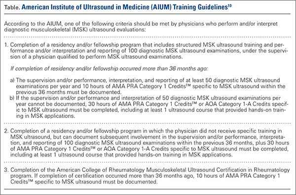
There are currently no certifications necessary to perform ultrasound scans or bill for them; however, some insurance carriers may require demonstrating relevant, documented training for reimbursement.3 Various organizations are trying to develop certifications and regulations for ultrasound to standardize the use of this modality. In the United States, the American Institute of Ultrasound in Medicine (AIUM) and the American Registry for Diagnostic Medical Sonography (ARDMS) provide guidelines and particular MSK ultrasound certifications.10,11
Basic Ultrasound Principles
The ultrasound machine creates electrical impulses that are turned into sound waves by piezoelectric crystals at the probe’s footprint. These sound waves bounce off tissues and return to the probe, where they are converted electronically to an image on the monitor. Depending on the echogenicity of the scanned tissue, the ultrasound beam will either reflect or be absorbed at different rates. This variance is transmitted on the monitor as a grayscale image. When ultrasound waves are highly reflective, like in bone or fat, they are characterized as hyperechoic. The opposite occurs when ultrasound waves are absorbed like in the fluid of a cystic cavity or joint effusion, and the image appears black. This is described as anechoic.12 Intermediate tissues such as tendons that are less reflective are seen as hypoechoic and appear gray. When a tissue has a similar echogenicity to its surrounding tissues, it is called isoechoic.12
The transducer is the scanning component of the ultrasound machine. Transducers come in 2 shapes: linear and curvilinear. The linear probe creates a straight image that is equal to the size of the transducer footprint. The curvilinear probe creates a wider, wedge-shaped panoramic image.
Linear probes are of higher frequency and generate higher resolution images of shallower structures, while curvilinear probes have greater depth penetration but generate lower resolution images. A high frequency of 10 to 15 MHz is preferred for anatomy between 2 cm to 4 cm depth.13 Midrange frequency of 5 to 10 MHz is preferred at 5 cm to 6 cm depth, and low-frequency 2 to 5 MHz probes are preferred for anatomical structures >6 cm depth.13
Anisotropy is the property of being directionally dependent, as opposed to isotropy, which implies identical properties in all directions. This anisotropic effect is dependent on the angle of the insonating beam. The maximum return echo occurs when the ultrasound beam is perpendicular to the tendon. Decreasing the insonating angle on a normal tendon will cause it to change from brightly hyperechoic (the actual echo from tightly bound tendon fibers) to darkly hypoechoic. If the angle is then increased, the tendon will again appear hyperechoic. If the artifact causes a normal tendon to appear hypoechoic, it may falsely lead to a diagnosis of tendinosis or tear.
Posterior acoustic shadowing is present when a hyperechoic structure reflects the ultrasound beam so much that it creates a dark shadow underneath it.12,14 This phenomenon is possible since the ultrasound beam cannot penetrate the hyperechoic structure and reflects off its inferior tissues. Reverberation is when the beam is repeated back and forth between 2 parallel highly reflective surfaces. The initial reflection will be displayed correctly, while the subsequent ultrasound waves will be delayed and appear at a farther distance from the transducer.12,14
The point where the beam is at its narrowest point generates the section of the image that is best visualized.15 This is called the focal zone, and it can be adjusted to highlight the desired area of evaluation. Gain controls adjust the amount of black, gray, and white on the monitor and can be adjusted to focus the desired image.13 Depth settings are fundamental in finding the desired targets. It is recommended to start with a higher depth setting to get an overview and progressively decrease the depth to key in on the desired anatomy.13 Color Doppler can be used to view movement within structures and to identify vessels, synovitis, and neovascularization in tendinopathy.13
Ultrasound of the Shoulder
Patients should be seated, if possible, on a rotating seat. The examiner’s shoulder should be higher than the patient’s shoulder.16 The user holds the ultrasound probe between the thumb and index fingers while resting the hypothenar eminence on the patient to serve as a fulcrum and steadying force. The examination should take 5 to 15 minutes, depending on the examiner’s expertise and the amount of anatomy being scanned.
Examining the body requires knowledge of anatomy. The examination and accuracy are determined by the technician using the probe. The probe can be angled any direction and be placed obliquely on the subject. The advantage here is that anatomy in the human body is not always planar. Muscles and tissues can run obliquely or even perpendicular to each other. When evaluating anatomy, the examiner should keep in mind what structure he or she is looking for; where it should be found; what landmarks can be used to easily locate it; what orientation it has; and what the normal anatomy should look like.
Muscle appears as a lattice with larger areas of hypoechoic muscle tissue and hyperechoic fascial perimysium layers traversing through it.17 The actual muscle tissue appears hypoechoic from the fluid or blood found within. Scarring, fibrosis, calcification, or chronic injury will change the tissue to appear denser or hyperechoic.17 Acute injury will appear hypoechoic from the inflammatory response and influx of blood. Tendon appears dense and hyperechoic with striations within the tissue, sometimes referred to as a horse’s tail.17 When torn, there will be a disassociation of the tissue with a hypoechoic region between the 2 ends. The attachment to the bone and muscle tissue should appear uniform. Hyperechoic areas within the tendon may be from calcification. Ligament appears similar to tendon but is more isoechoic and connects bone to bone. Evaluation of the entire length and the attachments to the bone are critical to evaluate for disease.
Bone appears bright hyperechoic, smooth, and flat, while hyaline cartilage is hypoechoic, smooth, and runs superiorly in a parallel pattern to its respective inferior cortical bone.17
Fibrocartilage is hyperechoic and typically triangularly shaped, such as in the glenohumeral labrum. Nerves appear fascicular and hypoechoic surrounded by hyperechoic epineurium.14
The epidermis and dermis are the most superficial structure on top of the screen, and are also hyperechoic.17
The Diagnostic Shoulder Examination
The proximal long head of the biceps tendon (LHBT) is the easiest structure in the shoulder to identify because of the anatomic structure, the bicipital groove. By keeping the arm relaxed, perpendicular to the ground, and in neutral rotation, the probe can be placed perpendicular to the arm over the proximal shoulder (Figure 1A).16-20 By finding the groove, the biceps tendon will usually be found resting within the groove (Figure 1B). This is the short axis view and is equivalent to an MRI in the axial plane.
The long axis view of the proximal biceps tendon is found by keeping the tendon in the center of the screen/probe. The probe is then rotated 90° on its center axis, keeping the tendon centered on the probe. The user should be sure to visualize the entire tendon on the screen. If only part of the tendon is seen along only part of the screen, then the probe is oblique to the tendon. In this case, the probe area showing the tendon must be stabilized as the center or set point. The other part of the probe will then pivot until all of the tendon is seen on the screen. The MRI equivalent to the long axis of the proximal biceps tendon is the sagittal view.
Ultrasound is a dynamic evaluation. Moving the probe or moving the patient will change what and how something is imaged. The proximal biceps tendon is a good example of this concept. The bicipital groove is very deep proximally and flattens out as it travels distally to the mid-humerus. The examiner should continually adjust his or her hand/probe/patient position as well as depth/gain and other console functions to adapt to the dynamics of the scan. While keeping the bicep tendon in a short axis view, the tendon can be dynamically evaluated for subluxation by internally and externally rotating the arm.
To find the subscapularis, the arm remains in a neutral position with the hand supinated and the probe is held parallel with the ground. After finding the bicipital groove, the subscapularis tendon insertion is just medial to the groove (Figure 1B). By externally rotating the arm, the subscapularis tendon/muscle will come into a long axis view.16-20 The MRI equivalent to the long axis view of the subscapularis is the axial view. Dynamic testing can be done by internally and externally rotating the arm to evaluate for impingement of the subscapularis tendon as it slides underneath the coracoid process. To view the subscapularis tendon in short axis, the tendon is kept in the center of the screen/probe, and the probe is then rotated 90° on its center axis, keeping the tendon centered on the probe. The MRI equivalent is the sagittal view.
Some have recommended using the modified Crass or Middleton position to evaluate the supraspinatus, where the hand is in the “back pocket”.19 However, many patients with shoulder pain have trouble with this position. By resting the ipsilateral hand on the ipsilateral hip and then dropping the elbow, the supraspinatus insertion can still be brought out from under the acromion. This does bring the insertion anterior out of the scapular plane, so an adjustment is required in probe positioning to properly see the supraspinatus short and long axis. To find the long axis, the probe is placed parallel to a plane that spans the contralateral shoulder and ipsilateral hip (Figure 2A). The fibers of the supraspinatus should be inserting directly lateral to the humeral head without any intervening space (Figure 2B). If any space exists, a partial articular supraspinatus tendon avulsion (PASTA) lesion is present, and its thickness can be directly measured. Moving more posterior will show the flattening of the tuberosity and the fibers of the infraspinatus moving away from the humeral head—the bare spot. The MRI equivalent is the coronal view.
To view the supraspinatus tendon in short axis, maintain the arm in the same position, keeping the tendon in the center of the screen/probe. The probe is then rotated 90° on its center axis, keeping the tendon centered on the probe. The probe should now be in a parallel plane between the ipsilateral shoulder and the contralateral hip. The biceps tendon in cross-section will be found anteriorly, and the articular cartilage will appear as a black layer over the bone. Dynamic testing includes placing the probe in a coronal plane between the acromion and greater tuberosity. When the patient abducts the arm while in internal rotation, the supraspinatus tendon will slide underneath the coracoacromial arch showing potential external impingement.15 The MRI equivalent is the sagittal plane.
The glenohumeral joint is best viewed posteriorly, limiting how much of the intra-articular portion of the joint can be imaged. The arm remains in a neutral position; palpate for the posterior acromion and place the probe just inferior to it, wedging up against it (Figure 3A). The glenohumeral joint will be seen by keeping the probe parallel to the ground (Figure 3B). The MRI equivalent is the axial plane. If a joint effusion exists, it can be seen in the posterior recess.15 A hyperechoic triangular region in between the humeral head and the glenoid will represent the glenoid labrum (Figure 3B). By internally and externally rotating the arm, the joint and labrum complex can be dynamically examined. From the labrum, scanning superior and medial can sometimes show the spinoglenoid notch where a paralabral cyst might be seen.15
Using the glenohumeral joint as a reference, the infraspinatus muscle is easily visualized. Maintaining the arm in neutral position with the probe over the glenohumeral joint, the infraspinatus will become apparent as it lays in long axis view superficially between the posterior deltoid and glenohumeral joint (Figure 3B).16-20 The teres minor lies just inferiorly. The MRI equivalent is the axial plane. To view the infraspinatus and teres minor in short axis, the probe is then rotated 90° on its center axis. The infraspinatus (superiorly) and teres minor (inferiorly) muscles will be visible in short axis within the infraspinatus fossa.15 The MRI equivalent is the sagittal view.
The acromioclavicular joint is superficial and easy to image. The arm remains in a neutral position, and we can palpate the joint for easy localization. The probe is placed anteriorly in a coronal plane over the acromion and clavicle. By scanning anteriorly and posteriorly, a joint effusion referred to as a Geyser sign might be seen. The MRI equivalent is the coronal view.
Available Certifications
The AIUM certification is a voluntary peer reviewed process that acknowledges that a practice is meeting national standards and aids in improving their respective MSK ultrasound protocols. They also provide guidelines on demonstrating training and competence on performing and/or interpreting diagnostic MSK examinations (Table).10 The ARDMS certification provides an actual individual certification referred to as “Registered” in MSK ultrasound.11 The physician must perform 150 diagnostic MSK ultrasound evaluations within 36 months of applying and pass a 200-question examination that is offered twice per year.11 None of these certifications are mandated by the American Medical Association (AMA) or American Osteopathic Association (AOA).
Maintenance and Continuing Medical Education (CME)
The AIUM recommends that a minimum of 50 diagnostic MSK ultrasound evaluations be performed per year for skill maintenance.10 Furthermore, 10 hours of AMA PRA Category 1 Credits™ or American Osteopathic Association Category 1-A Credits specific to MSK ultrasound must be completed by physicians performing and/or interpreting these examinations every 3 years.10 ARDMS recommends a minimum of 30 MSK ultrasound-specific CMEs in preparation for their “Registered” MSK evaluation.1
Conclusion
MSK ultrasound is a dynamic, real-time imaging modality that can improve cost efficiency and patient care. Its portability allows for its use anywhere. Learning the skill may seem daunting, but with the proper courses and education, the technology can be easily learned. By correlating a known modality like MRI, the user will easily begin to read ultrasound images. No current certification is needed to use or bill for ultrasound, but various institutions are developing criteria and testing. Two organizations, AIUM and ARDMS, provide guidelines and certifications to demonstrate competency, which may become necessary in the very near future.
1. Sivan M, Brown J, Brennan S, Bhakta B. A one-stop approach to the management of soft tissue and degenerative musculoskeletal conditions using clinic-based ultrasonography. Musculoskeletal Care. 2011;9(2):63-68.
2. Roy J-S, Braën C, Leblond J, et al. Diagnostic accuracy of ultrasonography, MRI and MR arthrography in the characterization of rotator cuff disorders: a meta-analysis [published online ahead of print February 11, 2015]. Br J Sports Med. doi:10.1136/bjsports-2014-094148.
3. Hirahara AM, Panero AJ. A guide to ultrasound of the shoulder, part 1: coding and reimbursement. Am J Orthop. 2016;45(3):176-182.
4. Hama M, Takase K, Ihata A, et al. Challenges to expanding the clinical application of musculoskeletal ultrasonography (MSUS) among rheumatologists: from a second survey in Japan. Mod Rheumatol. 2012;2:202-208.
5. Smith MJ, Rogers A, Amso N, Kennedy J, Hall A, Mullaney P. A training, assessment and feedback package for the trainee shoulder sonographer. Ultrasound. 2015;23(1):29-41.
6. Delzell PB, Boyle A, Schneider E. Dedicated training program for shoulder sonography: the results of a quality program reverberate with everyone. J Ultrasound Med. 2015;34(6):1037-1042.
7. Finnoff JT, Berkoff D, Brennan F, et al. American Medical Society for Sports Medicine (AMSSM) recommended sports ultrasound curriculum for sports medicine fellowships. PM R. 2015;7(2)e1-e11.
8. Adelman S, Fishman P. Use of portable ultrasound machine for outpatient orthopedic diagnosis: an implementation study. Perm J. 2013;17(3):18-22.
9. Vollman A, Hulen R, Dulchavsky S, et al. Educational benefits of fusing magnetic resonance imaging with sonograms. J Clin Ultrasound. 2014;42(5) 257-263.
10. Training guidelines for physicians and chiropractors who evaluate and interpret diagnostic musculoskeletal ultrasound examinations. Laurel, MD: American Institute of Ultrasound in Medicine; 2014. http://www.aium.org/resources/viewStatement.aspx?id=51. Accessed February 26, 2016.
11. Registered in musculoskeletal (RMSK) sonography. American Registry for Diagnostic Medical Sonography Web site. http://www.ardms.org/get-certified/RMSK/Pages/RMSK.aspx. Accessed February 26, 2016.
12. Silkowski C. Ultrasound nomenclature, image orientation, and basic instrumentation. In: Abraham D, Silkowski C, Odwin C, eds. Emergency Medicine Sonography Pocket Guide to Sonographic Anatomy and Pathology. Sudbury, MA: Jones and Bartlett; 2010:1-24.
13. Ihnatsenka B, Boezaart AP. Ultrasound: basic understanding and learning the language. Int J Shoulder Surg. 2010;4(3):55-62.
14. Taljanovic MS, Melville DM, Scalcione LR, Gimber LH, Lorenz EJ, Witte RS. Artifacts in musculoskeletal ultrasonography. Semin Musculoskelet Radiol. 2014;18(1):3-11.
15. Ng A, Swanevelder J. Resolution in ultrasound imaging. Continuing Educ Anaesth Crit Care Pain. 2011;11(5):186-192. http://ceaccp.oxfordjournals.org/content/11/5/186.full. Accessed March 3, 2016.
16. Nazarian L, Bohm-Velez M, Kan JH, et al. AIUM practice parameters for the performance of a musculoskeletal ultrasound examination. Laurel, MD: American Institute of Ultrasound in Medicine; 2012. http://www.aium.org/resources/guidelines/musculoskeletal.pdf. Accessed February 26, 2016.
17. Jacobson J. Fundamentals of Musculoskeletal Ultrasound. 2nd edition. Philadelphia, PA: Elsevier Saunders; 2013.
18. The Ultrasound Subcommittee of the European Society of Musculoskeletal Radiology. Musculoskeletal ultrasound: technique guidelines. Insights Imaging. 2010;1:99-141.
19. Corazza A, Orlandi D, Fabbro E, et al. Dynamic high-resolution ultrasound of the shoulder: how we do it. Eur J Radiol. 2015;84(2):266-277.
20. Allen GM. Shoulder ultrasound imaging-integrating anatomy, biomechanics and disease processes. Eur J Radiol. 2008;68(1):137-146
The musculoskeletal (MSK) ultrasound evaluation of the shoulder provides a cost- and time-efficient imaging modality with similar diagnostic power as magnetic resonance imaging (MRI).1,2 Its portable point-of-care applications can be used in the office, in the operating room, and in sideline athletic event coverage, as we discussed in Part 1 of this series.3
MSK ultrasound may seem difficult and daunting, and many articles have quoted steep learning curves.4,5 However, in our experience in teaching many ultrasound courses, this modality can be learned quite quickly with the proper instruction. Physicians are already familiar with anatomy and usually have had some exposure to MRI.4 Taking courses in MSK ultrasound or simply learning the basic concepts of ultrasound and then learning the machine controls is usually a good start.5-8 Practice scanning normal individuals, comparing the images from an MRI to learn how to reproduce the same planes and images. This will allow the user to become familiar with normal anatomy and how to see the images on the ultrasound screen.5-8 Vollman and colleagues9 showed that in trainees, combining MRI images with sonograms enhances the ability to correctly identify MSK ultrasound anatomy from 40.9% to 72.5%, when compared with learning from ultrasound images alone.
There are currently no certifications necessary to perform ultrasound scans or bill for them; however, some insurance carriers may require demonstrating relevant, documented training for reimbursement.3 Various organizations are trying to develop certifications and regulations for ultrasound to standardize the use of this modality. In the United States, the American Institute of Ultrasound in Medicine (AIUM) and the American Registry for Diagnostic Medical Sonography (ARDMS) provide guidelines and particular MSK ultrasound certifications.10,11
Basic Ultrasound Principles
The ultrasound machine creates electrical impulses that are turned into sound waves by piezoelectric crystals at the probe’s footprint. These sound waves bounce off tissues and return to the probe, where they are converted electronically to an image on the monitor. Depending on the echogenicity of the scanned tissue, the ultrasound beam will either reflect or be absorbed at different rates. This variance is transmitted on the monitor as a grayscale image. When ultrasound waves are highly reflective, like in bone or fat, they are characterized as hyperechoic. The opposite occurs when ultrasound waves are absorbed like in the fluid of a cystic cavity or joint effusion, and the image appears black. This is described as anechoic.12 Intermediate tissues such as tendons that are less reflective are seen as hypoechoic and appear gray. When a tissue has a similar echogenicity to its surrounding tissues, it is called isoechoic.12
The transducer is the scanning component of the ultrasound machine. Transducers come in 2 shapes: linear and curvilinear. The linear probe creates a straight image that is equal to the size of the transducer footprint. The curvilinear probe creates a wider, wedge-shaped panoramic image.
Linear probes are of higher frequency and generate higher resolution images of shallower structures, while curvilinear probes have greater depth penetration but generate lower resolution images. A high frequency of 10 to 15 MHz is preferred for anatomy between 2 cm to 4 cm depth.13 Midrange frequency of 5 to 10 MHz is preferred at 5 cm to 6 cm depth, and low-frequency 2 to 5 MHz probes are preferred for anatomical structures >6 cm depth.13
Anisotropy is the property of being directionally dependent, as opposed to isotropy, which implies identical properties in all directions. This anisotropic effect is dependent on the angle of the insonating beam. The maximum return echo occurs when the ultrasound beam is perpendicular to the tendon. Decreasing the insonating angle on a normal tendon will cause it to change from brightly hyperechoic (the actual echo from tightly bound tendon fibers) to darkly hypoechoic. If the angle is then increased, the tendon will again appear hyperechoic. If the artifact causes a normal tendon to appear hypoechoic, it may falsely lead to a diagnosis of tendinosis or tear.
Posterior acoustic shadowing is present when a hyperechoic structure reflects the ultrasound beam so much that it creates a dark shadow underneath it.12,14 This phenomenon is possible since the ultrasound beam cannot penetrate the hyperechoic structure and reflects off its inferior tissues. Reverberation is when the beam is repeated back and forth between 2 parallel highly reflective surfaces. The initial reflection will be displayed correctly, while the subsequent ultrasound waves will be delayed and appear at a farther distance from the transducer.12,14
The point where the beam is at its narrowest point generates the section of the image that is best visualized.15 This is called the focal zone, and it can be adjusted to highlight the desired area of evaluation. Gain controls adjust the amount of black, gray, and white on the monitor and can be adjusted to focus the desired image.13 Depth settings are fundamental in finding the desired targets. It is recommended to start with a higher depth setting to get an overview and progressively decrease the depth to key in on the desired anatomy.13 Color Doppler can be used to view movement within structures and to identify vessels, synovitis, and neovascularization in tendinopathy.13
Ultrasound of the Shoulder
Patients should be seated, if possible, on a rotating seat. The examiner’s shoulder should be higher than the patient’s shoulder.16 The user holds the ultrasound probe between the thumb and index fingers while resting the hypothenar eminence on the patient to serve as a fulcrum and steadying force. The examination should take 5 to 15 minutes, depending on the examiner’s expertise and the amount of anatomy being scanned.
Examining the body requires knowledge of anatomy. The examination and accuracy are determined by the technician using the probe. The probe can be angled any direction and be placed obliquely on the subject. The advantage here is that anatomy in the human body is not always planar. Muscles and tissues can run obliquely or even perpendicular to each other. When evaluating anatomy, the examiner should keep in mind what structure he or she is looking for; where it should be found; what landmarks can be used to easily locate it; what orientation it has; and what the normal anatomy should look like.
Muscle appears as a lattice with larger areas of hypoechoic muscle tissue and hyperechoic fascial perimysium layers traversing through it.17 The actual muscle tissue appears hypoechoic from the fluid or blood found within. Scarring, fibrosis, calcification, or chronic injury will change the tissue to appear denser or hyperechoic.17 Acute injury will appear hypoechoic from the inflammatory response and influx of blood. Tendon appears dense and hyperechoic with striations within the tissue, sometimes referred to as a horse’s tail.17 When torn, there will be a disassociation of the tissue with a hypoechoic region between the 2 ends. The attachment to the bone and muscle tissue should appear uniform. Hyperechoic areas within the tendon may be from calcification. Ligament appears similar to tendon but is more isoechoic and connects bone to bone. Evaluation of the entire length and the attachments to the bone are critical to evaluate for disease.
Bone appears bright hyperechoic, smooth, and flat, while hyaline cartilage is hypoechoic, smooth, and runs superiorly in a parallel pattern to its respective inferior cortical bone.17
Fibrocartilage is hyperechoic and typically triangularly shaped, such as in the glenohumeral labrum. Nerves appear fascicular and hypoechoic surrounded by hyperechoic epineurium.14
The epidermis and dermis are the most superficial structure on top of the screen, and are also hyperechoic.17
The Diagnostic Shoulder Examination
The proximal long head of the biceps tendon (LHBT) is the easiest structure in the shoulder to identify because of the anatomic structure, the bicipital groove. By keeping the arm relaxed, perpendicular to the ground, and in neutral rotation, the probe can be placed perpendicular to the arm over the proximal shoulder (Figure 1A).16-20 By finding the groove, the biceps tendon will usually be found resting within the groove (Figure 1B). This is the short axis view and is equivalent to an MRI in the axial plane.
The long axis view of the proximal biceps tendon is found by keeping the tendon in the center of the screen/probe. The probe is then rotated 90° on its center axis, keeping the tendon centered on the probe. The user should be sure to visualize the entire tendon on the screen. If only part of the tendon is seen along only part of the screen, then the probe is oblique to the tendon. In this case, the probe area showing the tendon must be stabilized as the center or set point. The other part of the probe will then pivot until all of the tendon is seen on the screen. The MRI equivalent to the long axis of the proximal biceps tendon is the sagittal view.
Ultrasound is a dynamic evaluation. Moving the probe or moving the patient will change what and how something is imaged. The proximal biceps tendon is a good example of this concept. The bicipital groove is very deep proximally and flattens out as it travels distally to the mid-humerus. The examiner should continually adjust his or her hand/probe/patient position as well as depth/gain and other console functions to adapt to the dynamics of the scan. While keeping the bicep tendon in a short axis view, the tendon can be dynamically evaluated for subluxation by internally and externally rotating the arm.
To find the subscapularis, the arm remains in a neutral position with the hand supinated and the probe is held parallel with the ground. After finding the bicipital groove, the subscapularis tendon insertion is just medial to the groove (Figure 1B). By externally rotating the arm, the subscapularis tendon/muscle will come into a long axis view.16-20 The MRI equivalent to the long axis view of the subscapularis is the axial view. Dynamic testing can be done by internally and externally rotating the arm to evaluate for impingement of the subscapularis tendon as it slides underneath the coracoid process. To view the subscapularis tendon in short axis, the tendon is kept in the center of the screen/probe, and the probe is then rotated 90° on its center axis, keeping the tendon centered on the probe. The MRI equivalent is the sagittal view.
Some have recommended using the modified Crass or Middleton position to evaluate the supraspinatus, where the hand is in the “back pocket”.19 However, many patients with shoulder pain have trouble with this position. By resting the ipsilateral hand on the ipsilateral hip and then dropping the elbow, the supraspinatus insertion can still be brought out from under the acromion. This does bring the insertion anterior out of the scapular plane, so an adjustment is required in probe positioning to properly see the supraspinatus short and long axis. To find the long axis, the probe is placed parallel to a plane that spans the contralateral shoulder and ipsilateral hip (Figure 2A). The fibers of the supraspinatus should be inserting directly lateral to the humeral head without any intervening space (Figure 2B). If any space exists, a partial articular supraspinatus tendon avulsion (PASTA) lesion is present, and its thickness can be directly measured. Moving more posterior will show the flattening of the tuberosity and the fibers of the infraspinatus moving away from the humeral head—the bare spot. The MRI equivalent is the coronal view.
To view the supraspinatus tendon in short axis, maintain the arm in the same position, keeping the tendon in the center of the screen/probe. The probe is then rotated 90° on its center axis, keeping the tendon centered on the probe. The probe should now be in a parallel plane between the ipsilateral shoulder and the contralateral hip. The biceps tendon in cross-section will be found anteriorly, and the articular cartilage will appear as a black layer over the bone. Dynamic testing includes placing the probe in a coronal plane between the acromion and greater tuberosity. When the patient abducts the arm while in internal rotation, the supraspinatus tendon will slide underneath the coracoacromial arch showing potential external impingement.15 The MRI equivalent is the sagittal plane.
The glenohumeral joint is best viewed posteriorly, limiting how much of the intra-articular portion of the joint can be imaged. The arm remains in a neutral position; palpate for the posterior acromion and place the probe just inferior to it, wedging up against it (Figure 3A). The glenohumeral joint will be seen by keeping the probe parallel to the ground (Figure 3B). The MRI equivalent is the axial plane. If a joint effusion exists, it can be seen in the posterior recess.15 A hyperechoic triangular region in between the humeral head and the glenoid will represent the glenoid labrum (Figure 3B). By internally and externally rotating the arm, the joint and labrum complex can be dynamically examined. From the labrum, scanning superior and medial can sometimes show the spinoglenoid notch where a paralabral cyst might be seen.15
Using the glenohumeral joint as a reference, the infraspinatus muscle is easily visualized. Maintaining the arm in neutral position with the probe over the glenohumeral joint, the infraspinatus will become apparent as it lays in long axis view superficially between the posterior deltoid and glenohumeral joint (Figure 3B).16-20 The teres minor lies just inferiorly. The MRI equivalent is the axial plane. To view the infraspinatus and teres minor in short axis, the probe is then rotated 90° on its center axis. The infraspinatus (superiorly) and teres minor (inferiorly) muscles will be visible in short axis within the infraspinatus fossa.15 The MRI equivalent is the sagittal view.
The acromioclavicular joint is superficial and easy to image. The arm remains in a neutral position, and we can palpate the joint for easy localization. The probe is placed anteriorly in a coronal plane over the acromion and clavicle. By scanning anteriorly and posteriorly, a joint effusion referred to as a Geyser sign might be seen. The MRI equivalent is the coronal view.
Available Certifications
The AIUM certification is a voluntary peer reviewed process that acknowledges that a practice is meeting national standards and aids in improving their respective MSK ultrasound protocols. They also provide guidelines on demonstrating training and competence on performing and/or interpreting diagnostic MSK examinations (Table).10 The ARDMS certification provides an actual individual certification referred to as “Registered” in MSK ultrasound.11 The physician must perform 150 diagnostic MSK ultrasound evaluations within 36 months of applying and pass a 200-question examination that is offered twice per year.11 None of these certifications are mandated by the American Medical Association (AMA) or American Osteopathic Association (AOA).
Maintenance and Continuing Medical Education (CME)
The AIUM recommends that a minimum of 50 diagnostic MSK ultrasound evaluations be performed per year for skill maintenance.10 Furthermore, 10 hours of AMA PRA Category 1 Credits™ or American Osteopathic Association Category 1-A Credits specific to MSK ultrasound must be completed by physicians performing and/or interpreting these examinations every 3 years.10 ARDMS recommends a minimum of 30 MSK ultrasound-specific CMEs in preparation for their “Registered” MSK evaluation.1
Conclusion
MSK ultrasound is a dynamic, real-time imaging modality that can improve cost efficiency and patient care. Its portability allows for its use anywhere. Learning the skill may seem daunting, but with the proper courses and education, the technology can be easily learned. By correlating a known modality like MRI, the user will easily begin to read ultrasound images. No current certification is needed to use or bill for ultrasound, but various institutions are developing criteria and testing. Two organizations, AIUM and ARDMS, provide guidelines and certifications to demonstrate competency, which may become necessary in the very near future.
1. Sivan M, Brown J, Brennan S, Bhakta B. A one-stop approach to the management of soft tissue and degenerative musculoskeletal conditions using clinic-based ultrasonography. Musculoskeletal Care. 2011;9(2):63-68.
2. Roy J-S, Braën C, Leblond J, et al. Diagnostic accuracy of ultrasonography, MRI and MR arthrography in the characterization of rotator cuff disorders: a meta-analysis [published online ahead of print February 11, 2015]. Br J Sports Med. doi:10.1136/bjsports-2014-094148.
3. Hirahara AM, Panero AJ. A guide to ultrasound of the shoulder, part 1: coding and reimbursement. Am J Orthop. 2016;45(3):176-182.
4. Hama M, Takase K, Ihata A, et al. Challenges to expanding the clinical application of musculoskeletal ultrasonography (MSUS) among rheumatologists: from a second survey in Japan. Mod Rheumatol. 2012;2:202-208.
5. Smith MJ, Rogers A, Amso N, Kennedy J, Hall A, Mullaney P. A training, assessment and feedback package for the trainee shoulder sonographer. Ultrasound. 2015;23(1):29-41.
6. Delzell PB, Boyle A, Schneider E. Dedicated training program for shoulder sonography: the results of a quality program reverberate with everyone. J Ultrasound Med. 2015;34(6):1037-1042.
7. Finnoff JT, Berkoff D, Brennan F, et al. American Medical Society for Sports Medicine (AMSSM) recommended sports ultrasound curriculum for sports medicine fellowships. PM R. 2015;7(2)e1-e11.
8. Adelman S, Fishman P. Use of portable ultrasound machine for outpatient orthopedic diagnosis: an implementation study. Perm J. 2013;17(3):18-22.
9. Vollman A, Hulen R, Dulchavsky S, et al. Educational benefits of fusing magnetic resonance imaging with sonograms. J Clin Ultrasound. 2014;42(5) 257-263.
10. Training guidelines for physicians and chiropractors who evaluate and interpret diagnostic musculoskeletal ultrasound examinations. Laurel, MD: American Institute of Ultrasound in Medicine; 2014. http://www.aium.org/resources/viewStatement.aspx?id=51. Accessed February 26, 2016.
11. Registered in musculoskeletal (RMSK) sonography. American Registry for Diagnostic Medical Sonography Web site. http://www.ardms.org/get-certified/RMSK/Pages/RMSK.aspx. Accessed February 26, 2016.
12. Silkowski C. Ultrasound nomenclature, image orientation, and basic instrumentation. In: Abraham D, Silkowski C, Odwin C, eds. Emergency Medicine Sonography Pocket Guide to Sonographic Anatomy and Pathology. Sudbury, MA: Jones and Bartlett; 2010:1-24.
13. Ihnatsenka B, Boezaart AP. Ultrasound: basic understanding and learning the language. Int J Shoulder Surg. 2010;4(3):55-62.
14. Taljanovic MS, Melville DM, Scalcione LR, Gimber LH, Lorenz EJ, Witte RS. Artifacts in musculoskeletal ultrasonography. Semin Musculoskelet Radiol. 2014;18(1):3-11.
15. Ng A, Swanevelder J. Resolution in ultrasound imaging. Continuing Educ Anaesth Crit Care Pain. 2011;11(5):186-192. http://ceaccp.oxfordjournals.org/content/11/5/186.full. Accessed March 3, 2016.
16. Nazarian L, Bohm-Velez M, Kan JH, et al. AIUM practice parameters for the performance of a musculoskeletal ultrasound examination. Laurel, MD: American Institute of Ultrasound in Medicine; 2012. http://www.aium.org/resources/guidelines/musculoskeletal.pdf. Accessed February 26, 2016.
17. Jacobson J. Fundamentals of Musculoskeletal Ultrasound. 2nd edition. Philadelphia, PA: Elsevier Saunders; 2013.
18. The Ultrasound Subcommittee of the European Society of Musculoskeletal Radiology. Musculoskeletal ultrasound: technique guidelines. Insights Imaging. 2010;1:99-141.
19. Corazza A, Orlandi D, Fabbro E, et al. Dynamic high-resolution ultrasound of the shoulder: how we do it. Eur J Radiol. 2015;84(2):266-277.
20. Allen GM. Shoulder ultrasound imaging-integrating anatomy, biomechanics and disease processes. Eur J Radiol. 2008;68(1):137-146